Monthly Archives: พฤษภาคม 2016

เมนูหน้าเครื่อง HP deskjet ink advantage 3545

สำหรับผู้ใช้งานทั่วไป


hp deskjet ink advantage 3545
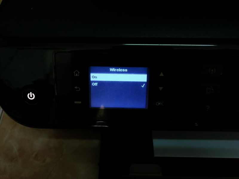
เปิดเครื่อง รอสักพัก
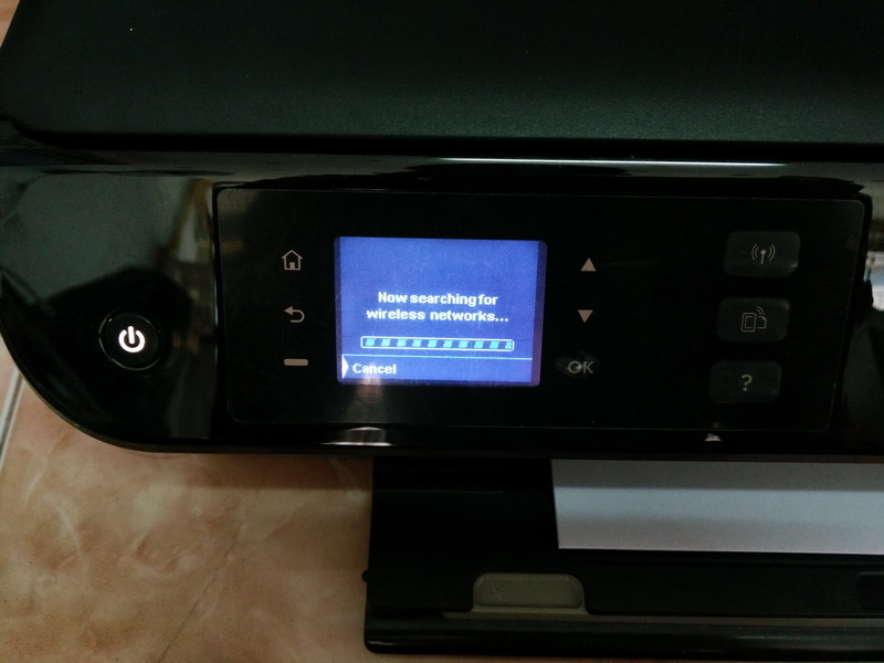
การใช้เครื่องครั้งแรก ต้องจัดแนวหัวพิมพ์ก่อน เพื่อให้ได้คุณภาพที่ดีในการปริ้นงาน

hp deskjet ink advantage 3545_01


เมื่อใส่ตลับหมึกเรียบร้อยแล้ว ให้ใส่กระดาษเข้าเครื่อง เพื่อเริ่มตั้งค่า กด OK

hp deskjet ink advantage 3545_02

hp deskjet ink advantage 3545_03

รอจนเครื่องปริ้นลายเส้นตัวอย่าง สำหรับตั้งค่าหัวพิมพ์ เสร็จ

hp deskjet ink advantage 3545_04

ให้หันคว่ำหน้ากระดาษ ให้ถูกทิศทาง แล้วปิด เพื่อดำเนินการต่อ

hp deskjet ink advantage 3545_05

กด OK

hp deskjet ink advantage 3545_06

รอสักครู่

hp deskjet ink advantage 3545_07

การจัดแนวหัวพิมพ์เสร็จแล้ว กดOK เพื่อเริ่มใช้งานตามปกติได้เลย

hp deskjet ink advantage 3545_08

เมนูต่างๆ ของเครื่องปริ้นรุ่นนี้..

hp deskjet ink advantage 3545_09

hp deskjet ink advantage 3545_10

hp deskjet ink advantage 3545_11

การตรวจสอบระดับน้ำหมึก

hp deskjet ink advantage 3545_12

hp deskjet ink advantage 3545_13

การตั้งค่าเชื่อมต่อไวไฟ

hp deskjet ink advantage 3545_14

เปิดไวไฟ

hp deskjet ink advantage 3545_15

ค้นหาสัญญาณไวไฟ

hp deskjet ink advantage 3545_16

เลือกไวไฟที่ต้องการ

hp deskjet ink advantage 3545_17

ใสรหัสผ่านไวไฟ

hp deskjet ink advantage 3545_18

สถานะตลับหมึก

hp deskjet ink advantage 3545_19


ขอขอบคุณ

สาคอมพิวเตอร์ ระยอง

รายละเอียดไบออส GIGABYTE MAINBOARD

สำหรับผู้ใช้งานระดับสูง

กดปุ่ม Del. เข้าหน้าไบออส หลังจากกดเปิดเครื่อง

ไบออส GIGABYTE MAINBOARD GA-H81M

Gigabyte-H81-Bios01

Gigabyte-H81-Bios02

Gigabyte-H81-Bios03

Gigabyte-H81-Bios04

Gigabyte-H81-Bios05

ไบออส GIGABYTE MAINBOARD GA-Z170X-Gaming 3

Gigabyte-Z170-01

Gigabyte-Z170-02

Gigabyte-Z170-03

Gigabyte-Z170-04

Gigabyte-Z170-05

Gigabyte-Z170-06

Gigabyte-Z170-07


ตัวอย่างเป็นการปรับโหมด SATA AHCI ในหน้า Peripherals

Gigabyte-Bios


ขอขอบคุณ

สาคอมพิวเตอร์ ระยอง

Dell Optiplex 745 LED Diagnostic Lights – System Lights

สำหรับผู้ใช้งานระดับสูง

ตัวอย่างสัญญาณไฟหน้าเครื่อง แจ้งจุดเสีย…ของเครื่องคอมพิวเตอร์เดล… รุ่นตัวอย่างและรุ่นอื่นๆ


dell-diag_leds_lagacyPower Button LEDs
Power Button LED State Description
Off Off Power is Off. LED is blank.
Blinking Amber Blinking Amber Initial State of LED at power up. Refer to the table below for Blinking Amber pattern diagnostic suggestions and possible failures.
Solid Amber Solid Amber The second state of the LED at power up, indicates that the POWER_GOOD signal is active and it is probable that the power supply is fine.
Blinking White Blinking White System is in a low power state, either S1 or S3. This does not indicate a fault condition.
Solid White Solid White System is in S0 state. This is the normal power states of a functioning machine. The BIOS will turn the LED to this states to indicate it has started fetching op-codes.


Light Pattern Problem
Description
Suggested Resolution
Diagnostic LEDs Power
Button LED
The computer is either turned off or not receiving power.
  • Reseat the power cable in the power connector on the back of the computer and the electrical outlet.
  • Bypass power strips, power extension cables, and other power protection devices to verify that the computer turns on properly.
  • Ensure that any power strips being used are plugged into an electrical outlet and are turned on.
  • Ensure that the electrical outlet is working by testing it with another device, such as a lamp.
  • Ensure that the main power cable and front panel cable are securely connected to the system board.
A possible system board failure has occurred.
  • Unplug the computer. Allow one minute for the power to drain. Plug the computer into a working electrical outlet and press the power button.

Blinking
A possible system board, power supply, or peripheral failure has occurred.
  • Power off computer, leaving the computer plugged in. Press and hold the power supply test button on the rear of the power supply unit. If the LED next to the switch illuminates, the problem may be with your system board.
  • If the LED next to the switch does not illuminate, disconnect all internal and external peripherals, and press and hold the power supply test button.If it illuminates, there could be a problem with a peripheral.
  • If the LED still does not illuminate, remove the PSU connections from the system board, then press and hold the power supply button. If it illuminates, there could be a problem with the system board.
  • If the LED still does not illuminate, the problem is probably with the power supply.
No CPU present.
  • Reinstall the CPU and restart the system. If the computer still fails to boot, inspect the CPU socket for damage.
Memory modules are detected, but a memory power failure has occurred.
  • If two or more memory modules are installed, remove the modules, then reinstall one module and restart the computer. If the computer starts normally, continue to install additional memory modules (one at a time) until you have identified a faulty module or reinstalled all modules without error. If only one memory module is installed, try moving it to a different DIMM connector and restart the computer.
  • If available, install verified working memory of the same type into your computer.
A possible CPU or system board failure has occurred.
  • Replace the CPU with a known good CPU. If the computer still fails to boot, inspect the CPU socket for damage.
BIOS may be corrupt or missing.
  • The computer hardware is operating normally but the BIOS may be corrupt or missing.
A possible system board failure has occurred.
  • Remove all peripheral cards from the PCI and PCI-E slots and restart the computer. If the computer boots, add the peripheral cards back one by one until you find the bad one.
Power connector not installed properly.
  • Reseat the 2×2 power connector from the power supply unit.
Possible peripheral card or system board failure has occurred.
  • Remove all peripheral cards from the PCI and PCI-E slots and restart the computer. If the computer boots, add the peripheral cards back one by one until you find the bad one.
A possible system board failure has occurred.
  • Disconnect all internal and external peripherals, and restart the computer. If the computer boots, add the peripheral cards back one by one until you find the bad one.
  • If the problem persists, the system board is probably bad.
A possible coin cell battery failure has occurred.
  • Remove the coin cell battery for one minute, reinstall the battery, and restart.
The computer is in a normal on condition. The diagnostic lights are not lit after the computer successfully boots to the operating system.
  • Ensure that the display is connected and powered on.
A possible processor failure has occurred.
  • Reseat the processor.
Memory modules are detected, but a memory failure has occurred.
  • If two or more memory modules are installed, remove the modules (see your service manual), then reinstall one module (see your service manual and restart the computer. If the computer starts normally, continue to install additional memory modules (one at a time) until you have identified a faulty module or reinstalled all modules without error.
  • If available, install working memory of the same type into your computer.
A possible graphics card failure has occurred.
  • Reseat any installed graphics cards.
  • If available, install a working graphics card into your computer.
A possible floppy drive or hard drive failure has occurred.
  • Reseat all power and data cables.
A possible USB failure has occurred.
  • Reinstall all USB devices and check all cable connections.
No memory modules are detected.
  • If two or more memory modules are installed, remove the modules (see your service manual), then reinstall one module (see your service manual) and restart the computer. If the computer starts normally, continue to install additional memory modules (one at a time) until you have identified a faulty module or reinstalled all modules without error.
  • If available, install working memory of the same type into your computer.
Memory modules are detected, but a memory configuration or compatibility error has occurred.
  • Ensure that no special requirements for memory module/connector placement exist.
  • Ensure that the memory you are using is supported by your computer.
A possible expansion card failure has occurred.
  • Determine if a conflict exists by removing an expansion card (not a graphics card) and restarting the computer.
  • If the problem persists, reinstall the card you removed, then remove a different card and restart the computer.
  • Repeat this process for each expansion card installed. If the computer starts normally, troubleshoot the last card removed from the computer for resource conflicts.
A possible system board resource and/or hardware failure has occurred.
  • Clear CMOS.
  • Disconnect all internal and external peripherals, and restart the computer. If the computer boots, add the peripheral cards back one by one until you find the bad one.
  • If the problem persists, the system board / system board component is probably bad.
Another failure has occurred.
  • Ensure that all hard drive and optical drive cables are properly connected to the system board.
  • If there is an error message on the screen identifying a problem with a device (such as the floppy drive or hard drive), check the device to make sure it is functioning properly.
  • If the operating system is attempting to boot from a device (such as the floppy drive or optical drive), check system setup to ensure the boot sequence is correct for the devices installed on your computer.

System Lights

Your power button light and hard-drive light may indicate a computer problem.

Power Light

Problem Description

Suggested Resolution

Solid green Power is on, and the computer is operating normally. On the desktop computer, a solid green light indicates a network connection. No corrective action is required.
Blinking green The computer is in a power-saving mode (Microsoft® Windows® XP). Press the power button, move the mouse, or press a key on the keyboard to wake the computer.
Blinks green several times and then turns off A configuration error exists. Check the diagnostic lights to see if the specific problem is identified (see Diagnostic Lights).
Solid yellow The Dell Diagnostics is running a test, or a device on the system board may be faulty or incorrectly installed. If the Dell Diagnostics is running, allow the testing to complete.If the computer does not boot, contact Dell for technical assistance (see Contacting Dell).
Blinking yellow A power supply or system board failure has occurred. See Power Problems.
Solid green and a beep code during POST A problem was detected while the BIOS was executing. See Beep Codes for instructions on diagnosing the beep code. Also, check the diagnostic lights to see if the specific problem is identified (see Diagnostic Lights).
Solid green power light and no beep code and no video during POST The monitor or the graphics card may be faulty or incorrectly installed. Check the diagnostic lights to see if the specific problem is identified (see Diagnostic Lights).See Video and Monitor Problems.
Solid green power light and no beep code but the computer locks up during POST An integrated system board device may be faulty. Check the diagnostic lights to see if the specific problem is identified (see Diagnostic Lights). If the problem is not identified, contact Dell for technical assistance (see Contacting Dell).


ขอขอบคุณ

สาคอมพิวเตอร์ ระยอง

Dell™ OptiPlex™ 780 Service Manual : สถานะไฟ LED กระพริบ

สำหรับผู้ใช้งานระดับสูง


Dell Diagnostics Main Menu

  1. After the Dell Diagnostics loads and the Main Menu screen appears, click the button for the option you want.

Option

Function 

Express Test Performs a quick test of devices. This test typically takes 10 to 20 minutes and requires no interaction on your part. Run Express Test first to increase the possibility of tracing the problem quickly.
Extended Test Performs a thorough check of devices. This test typically takes 1 hour or more and requires you to answer questions periodically.
Custom Test Tests a specific device. You can customize the tests you want to run.
Symptom Tree Lists the most common symptoms encountered and allows you to select a test based on the symptom of the problem you are having.
  1. If a problem is encountered during a test, a message appears with an error code and a description of the problem. Write down the error code and problem description and follow the instructions on the screen.
  1. If you run a test from the Custom Test or Symptom Tree option, click the applicable tab described in the following table for more information.

Tab

Function 

Results Displays the results of the test and any error conditions encountered.
Errors Displays error conditions encountered, error codes, and the problem description.
Help Describes the test and may indicate requirements for running the test.
Configuration Displays your hardware configuration for the selected device.

The Dell Diagnostics obtains configuration information for all devices from system setup, memory, and various internal tests, and it displays the information in the device list in the left pane of the screen. The device list may not display the names of all the components installed on your computer or all devices attached to your computer.

Parameters Allows you to customize the test by changing the test settings.
  1. When the tests are completed, if you are running the Dell Diagnostics from the Drivers and Utilities disc, remove the disc.
  2. Close the test screen to return to the Main Menu screen. To exit the Dell Diagnostics and restart the computer, close the Main Menu screen.

Power Button Light Codes

The diagnostic lights give much more information about the system state, but legacy power light states are also supported in your computer. The power light states are shown in following table.

Power Light State Description
Off
Picture of the diagnostic Power LED in the Off state.
Power is off, light is blank.
Blinking Amber
Picture of the diagnostic Power LED in the Blinking Amber state.
Initial state of light at power up.
Indicates system has power, but the POWER_GOOD signal is not yet active.
If the Hard Drive light is off, it is probable that the power supply needs to be replaced.
If the Hard Drive light on, it is probable that an onboard regulator or VRM has failed. Look at the diagnostic lights for further information.
Solid Amber
Picture of the diagnostic Power LED in the Solid Amber state.
Second state of the light at power up. Indicates the POWER_GOOD signal is active and it is probable that the power supply is fine. Look at the diagnostic lights for further information.
Blinking Green
Picture of the diagnostic Power LED in the Blinking Green state.
System is in a low power state, either S1 or S3. Look at the diagnostic lights to determine which state the system is in.
Solid Green
Picture of the diagnostic Power LED in the Solid Green state.
System is in S0 state, the normal power state of a functioning machine.
The BIOS will turn the light to this state to indicate it has started fetching op-codes.

Beep Codes

If the monitor cannot display error messages during the POST, the computer may emit a series of beeps that identifies the problem or that can help you identify a faulty component or assembly. The following table lists the beep codes that may be generated during the POST. Most beep codes indicate a fatal error that prevents the computer from completing the boot routine until the indicated condition is corrected.

Code

Cause

1-1-2 Microprocessor register failure
1-1-3 NVRAM read/write failure
1-1-4 ROM BIOS checksum failure
1-2-1 Programmable interval timer failure
1-2-2 DMA initialization failure
1-2-3 DMA page register read/write failure
1-3 Video Memory Test failure
1-3-1 through 2-4-4 Memory not being properly identified or used
3-1-1 Slave DMA register failure
3-1-2 Master DMA register failure
3-1-3 Master interrupt mask register failure
3-1-4 Slave interrupt mask register failure
3-2-2 Interrupt vector loading failure
3-2-4 Keyboard Controller Test failure
3-3-1 NVRAM power loss
3-3-2 Invalid NVRAM configuration
3-3-4 Video Memory Test failure
3-4-1 Screen initialization failure
3-4-2 Screen retrace failure
3-4-3 Search for video ROM failure
4-2-1 No timer tick
4-2-2 Shutdown failure
4-2-3 Gate A20 failure
4-2-4 Unexpected interrupt in protected mode
4-3-1 Memory failure above address 0FFFFh
4-3-3 Timer-chip counter 2 failure
4-3-4 Time-of-day clock stopped
4-4-1 Serial or parallel port test failure
4-4-2 Failure to decompress code to shadowed memory
4-4-3 Math-coprocessor test failure
4-4-4 Cache test failure

Diagnostic Lights

To help troubleshoot a problem, your computer has four lights labeled 1, 2, 3, and 4 on the bank panel. When the computer starts normally, the lights flash before turning off. If the computer malfunctions, the sequence of the lights help to identify the problem.

NOTE: After the computer completes POST, all four lights turn off before booting to the operating system.

Light Pattern 

Problem Description

Suggested Resolution

The computer is in a normal off condition or a possible pre-BIOS failure has occurred.

The diagnostic lights are not lit after the computer successfully boots to the operating system.

  • Plug the computer into a working electrical outlet.
  • If the problem persists, contact Dell.
A possible processor failure has occurred.
  • Reseat the processor (see Processor information for your computer).
  • If the problem persists, contact Dell.
Memory modules are detected, but a memory failure has occurred.
  • If two or more memory modules are installed, remove the modules, then reinstall one module and restart the computer. If the computer starts normally, continue to install additional memory modules (one at a time) until you have identified a faulty module or reinstalled all modules without error.
  • If available, install working memory of the same type into your computer.
  • If the problem persists, contact Dell.
A possible graphics card failure has occurred.
  • Reseat any installed graphics cards.
  • If available, install a working graphics card into your computer.
  • If the problem persists, contact Dell .
A possible floppy drive or hard drive failure has occurred. Reseat all power and data cables.
A possible USB failure has occurred. Reinstall all USB devices and check all cable connections.
No memory modules are detected.
  • If two or more memory modules are installed, remove the modules, then reinstall one module and restart the computer. If the computer starts normally, continue to install additional memory modules (one at a time) until you have identified a faulty module or reinstalled all modules without error.
  • If available, install working memory of the same type into your computer.
  • If the problem persists, contact Dell.
Memory modules are detected, but a memory configuration or compatibility error has occurred.
  • Ensure that no special requirements for memory module/connector placement exist.
  • Ensure that the memory you are using is supported by your computer (see the “Specifications” section for your computer).
  • If the problem persists, contact Dell.
A possible expansion card failure has occurred.
  • Determine if a conflict exists by removing an expansion card (not a graphics card) and restarting the computer.
  • If the problem persists, reinstall the card you removed, then remove a different card and restart the computer.
  • Repeat this process for each expansion card installed. If the computer starts normally, troubleshoot the last card removed from the computer for resource conflicts.
  • If the problem persists, contact Dell.
Another failure has occurred.
  • Ensure that all hard drive and optical drive cables are properly connected to the system board .
  • If there is an error message on the screen identifying a problem with a device (such as the floppy drive or hard drive), check the device to make sure it is functioning properly.
  • If the operating system is attempting to boot from a device (such as the floppy drive or optical drive), check system setup to ensure the boot sequence is correct for the devices installed on your computer.
  • If the problem persists, contact Dell.

Back to Contents Page